Plywood Brackets Revisited
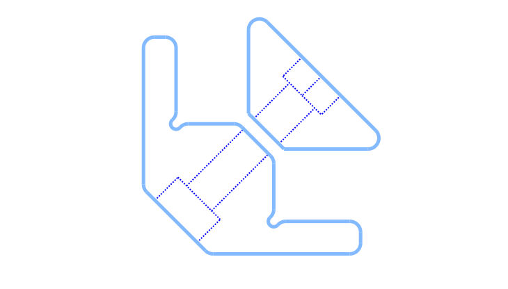
So much has changed in cadquery since I last used it in around 2022. Now we have the sketch API and assembly support
Since I wasn’t completely happy with my originalplywood brackets, I revised the model, this time taking advantage of the Sketch API.
The changes I wanted to implement were increased bearing area for the plywood board and small notches where the board corners rest. Since those locations act as stress concentrators, that’s where this component tends to fail and relieving stress there is important.
This new version also makes better use of parametric features to simplify tailoring the bracket so it clamps the plywood board while leaving only a minimal gap between the 3d printed bracket and jaw after the screw is tightened. In the script, I called the parameter that controls this gap “magic_margin”.
While everything could arguably be implemented using only boolean operations on 3D features, it was more straighfoward to do it using the 2D sketch methods.
Here’s the code:
#!/usr/bin/env python3

import cadquery as cq
from cadquery.vis import show

### Bookshelf Connectors for Plywood Boards

## Parameters
# Bracket parameters
tab_length = 40.0       # mm, tab length counting from the origin (part bounding box size)
tab_height = 6.0        # mm, height of the cantilever tab (tab thickness)
ply_thick = 12.0        # mm, thickness of wooden boards
bracket_width = 16.0    # mm, width of the bracket and jaw
outer_chamfer = 12.0    # mm, big chamfer on the lower left corner, creates the counterbore face
global_fillet = 2.0     # mm, radius of the fillet on edges perpendicular to Z axis
relief_radius = 1.0     # mm, radius of the semi-holes to relief vertices stress concentration
magic_margin = 0.5      # mm, clearance on the diagonal gaps for proper clamping

# Bracket hardware parameters (couterbore for the screw)
screw_clearance = 6.5   # mm, diameter of the screw + some fit clearance (M6 = 6.5 | M4 = 4.2)
screwHead_height = 6.0  # mm, screw head height (M6 = 6.0 | M4 = 4.0)
cBore_diameter = 11.0   # mm, screw cap diameter + some fit clearance (M6 = 11.0 | M4 = 7.5)
#
# Jaw hardware parameters (hex nut slot)
nut_width_AC = 11.5     # mm, width across corners (circumscribed diameter)(M6 = 11.5 | M4 = 8.5)
nut_thickness = 5.0     # mm, nut thickness  (M6 = 5.0 | M4 = 3.5)

# Pre defined parameters
inner_chamfer =  tab_height+magic_margin

tabs  = (cq.Sketch()
         .segment((0, 0), (0, tab_length))
         .segment((0, tab_length), (tab_height, tab_length))
         .segment((tab_height, tab_length), (tab_height, tab_height))
         .segment((tab_height, tab_height), (tab_length, tab_height))
         .segment((tab_length, tab_height), (tab_length, 0))
         .close()
         .assemble()
         .clean()
         .reset()
         .vertices(s="<X and <Y").chamfer(outer_chamfer)
         )

ply_bearing = (cq.Sketch()
              .segment((tab_height, tab_height),
                       (tab_height, 2*tab_height+ply_thick))
              .segment((tab_height, 2*tab_height+ply_thick),
                       (2*tab_height+ply_thick, 2*tab_height+ply_thick))
              .segment((2*tab_height+ply_thick, 2*tab_height+ply_thick),
                       (2*tab_height+ply_thick, tab_height))
              .close()
              .assemble()
              .clean()
              .reset()
              .vertices(s=">X and >Y").chamfer(inner_chamfer)
              )

relief = (cq.Sketch().push([(tab_height, 2*tab_height+ply_thick),
                            (2*tab_height+ply_thick, tab_height)]).
          circle(relief_radius)
          )

final_sketch = tabs.face(ply_bearing, mode='a').face(relief, mode='s')

bracket = (cq.Workplane("front").placeSketch(final_sketch).extrude(bracket_width/2, both=True)
           .faces("<(1, 1, 0)").workplane(centerOption="CenterOfMass")
           .cboreHole(screw_clearance, cBore_diameter, screwHead_height)
           .edges("|Z").fillet(global_fillet)
           )

jaw  = (cq.Workplane("front").sketch()
        .segment((0, 0), (0, tab_length/1.5))
        .segment((0, tab_length/1.5), (tab_length/1.5, 0))
        .close()
        .assemble()
        .clean()
        .vertices(s="<X and <Y")
        .chamfer(inner_chamfer)
        .finalize()
        .extrude(bracket_width/2, both=True)
        .faces("<(1, 1, 0)").workplane(centerOption="CenterOfMass").hole(screw_clearance)
        .faces(">(1, 1, 0)").workplane(centerOption="CenterOfMass")
        .transformed(rotate=cq.Vector(0, 0, 90)).polygon(6, nut_width_AC)
        .cutBlind(-nut_thickness)
        .edges("|Z and >Y").fillet(global_fillet)
        .edges("|Z and >X").fillet(global_fillet)
       )

jaw = jaw.translate((19.0, 19.0, 0))

assy = cq.Assembly(name="plywood-connectors")
assy.add(bracket, color=cq.Color(130/255.0, 185/255.0, 255/255.0), name="bracket")
assy.add(jaw, color=cq.Color(150/255.0, 255/255.0, 41/255.0), name="jaw")

show(assy)
- The cool line to pay attention here is the following one, where sketches are added and subtracted from the other.
final_sketch = tabs.face(ply_bearing, mode='a').face(relief, mode='s')
- Also usefull to know that you can use vector directions to select a face, This was used many times on the script as some important faces are oriented at 45 degrees. For example in:
.faces("<(1, 1, 0)").workplane(centerOption="CenterOfMass").hole(screw_clearance)
The assembly (assy) part was not necessary for such a simple model, but I included here as simple example of how to call it.
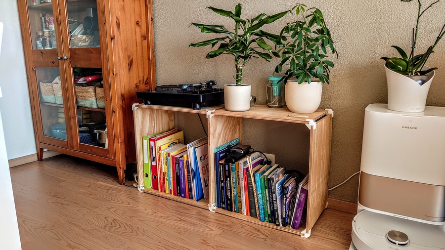
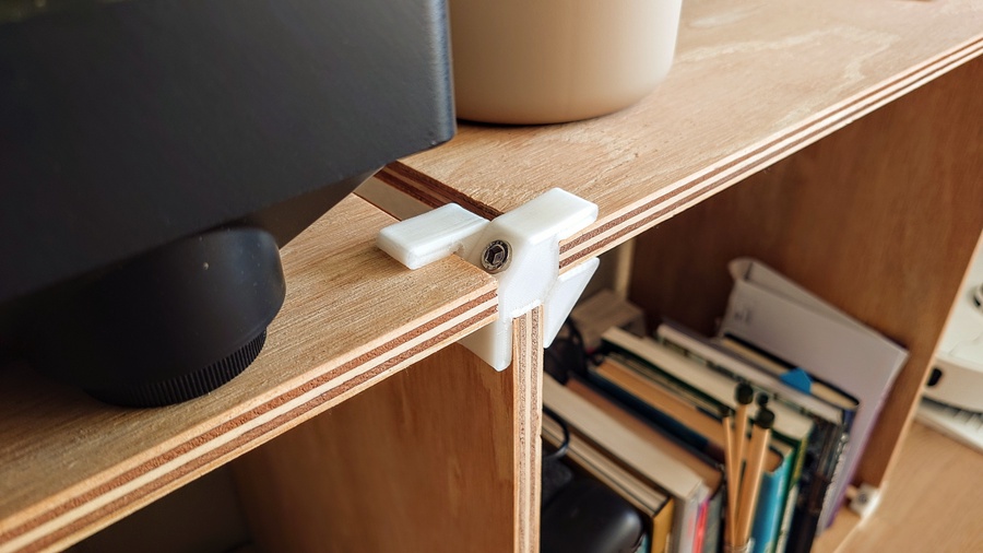
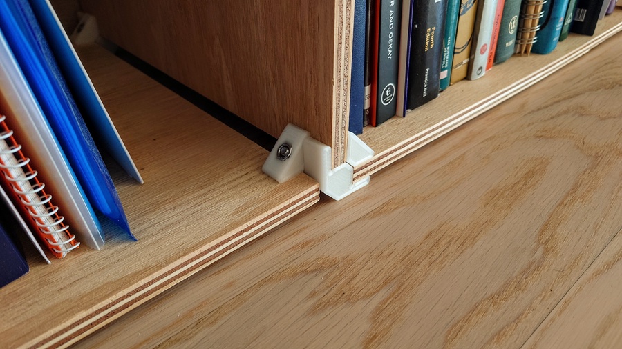
I used 12 mm plywood, 6 mm hardware and a special high toughness PLA. Considering it has no bracing, it’s reasonably strong and stable. Overall, I’m very happy with it — my turntable, along with books and loads of random stuff, regularly sit on top of it without any issues.
📎 Download: Plywood Bracket - M6 step file