Cable Strain Relief Mold in CadQuery, Ten Years Later
Why do I keep a blog? I get this question quite often from people who Google my name and discover that I have a blog. So here’s the long answer
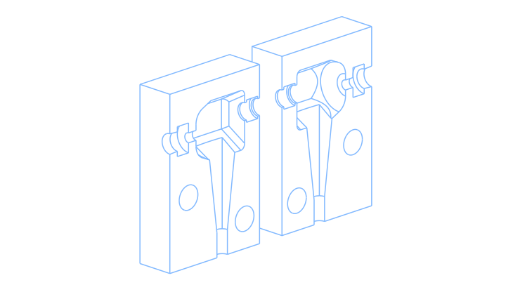
The opening drawing you see above is a resin mold for a prototype of a right-angle strain relief for 3.5 mm audio plugs that I designed roughly ten years ago (around 2016–2017). At the time, I already had professional experience with point-and-click 3D CAD packages, but to me that was the past. Text-based CAD had to be the future. I wasn’t anticipating theLarge Language Model revolution, but I wanted to explore the possibility of having something similar toTest-Driven Development for mechanical design.
Think about an aircraft project and all its complexity. In aerospace, moving from the Imperial system to the Metric system is often seen as unfeasible because of all the issues that could arise from such a change. Now imagine a more utopian world where the entire project was text-based and all the tests were written accordingly. AnAI agent could analyze the project and quickly identify all the pain points that would emerge from such a large-scale refactoring.
The aerospace industry is highly regulated, and for that reason it will probably never change, some might argue; I know, I have been there. But large engineering projects could, at least in principle, benefit from having their specifications expressed in a form that can be automatically verified. If the design evolves, the tests should tell you whether it still satisfies the requirements. That was my mindset at the time, and it was the reason I moved away from commercial, mouse-driven CAD packages.
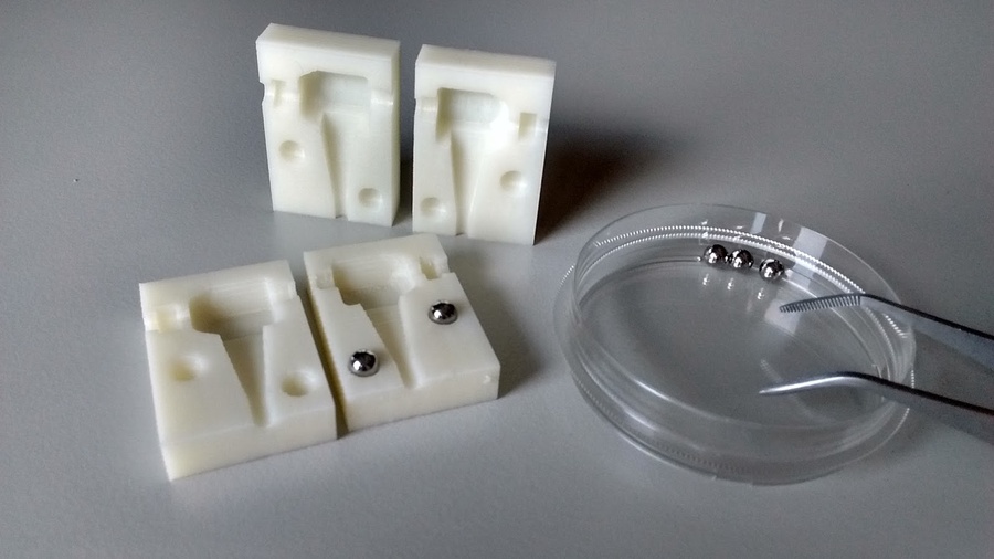
In that context, I simply wanted to gain more experience writing code to generate 3D models, and I was assigned to design a cable strain relief. I used CadQuery to create the mold for a resin prototype and posted it online. It was a very simple project, and my coding skills were still quite limited. Yet the internet somehow found it, liked it, and the rest is history.
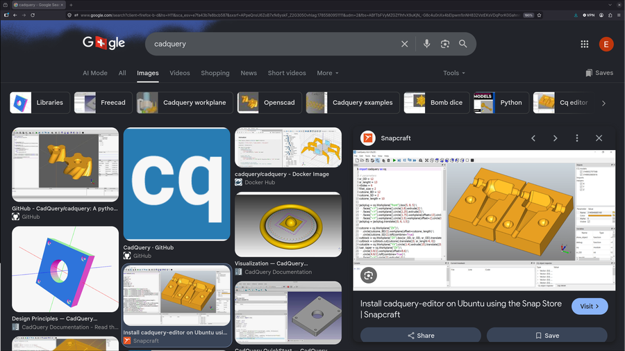
That model stayed on CadQuery’s GitHub front page for many years and was only removed recently. Nevertheless, even today, almost ten years later, if you Google “cadquery” and switch to the Images tab, there’s a good chance you’ll still see that model.
To be more explicit about why I write blog posts: people might find interesting the same things that I find interesting.
Sometimes it’s fun to randomly stumble across something you created years ago. A good example of this is theHP-50g code to compute air compressibility factor that I’ve written inRPL around 2010. At some point, someone found it and uploaded it tohpcalc.org.
<< HEAD(INFORM("air compressibility factor",{{"T:","Kelvin",0},{"P:","bar",0}},{1,0},{},{})) \-> L
    << L(1) -> T
        << L(2) -> P
            << 1|>Z ; P/37.71|>Pr ; T/132.65|>Tr ; .00001|>Ge ;
            DO .08664*Pr/(Z*Tr)|>k ; 1/(1-k)-4.9339796/Tr^1.5*(k/(1+k))|>Zrk ; Z-Zrk|>E ; Zrk|>Z ;
            UNTIL Ge>E
            END ; PURGE({'E','Ge','Zrk','k','Tr','Pr'}) ; Z
        >>
    >>
>>
That’s the main reason—but not the only one.
A second reason is that my blog serves as a collection of snapshots from my hobby projects. Every now and then, it’s nice to look back and think, “Oh geez, I remember this one.” The strain relief project is a perfect example. Recently, I had to design another strain relief for a different project involving a power cord, which I may write about in the future.
What is a cable strain relief? If you’ve read this far and are asking yourself that question, chances are you’ve seen one before without realizing it. In a connector, it is the part that provides the transition between the stiff metallic plug and the flexible cable. A very common implementation is the slotted, tapered plastic sleeve found on many patch cables, like the ones on this synth.

When you repeatedly bend a cable, the sharper the bend, the faster you’re gonna break it. That’s why strain reliefs exist: they prevent sharp bends from occurring at the point where the cable meets the connector.
Thinking like an engineer, imagine a rigid component connected directly to a flexible one. If you were to plot stiffness along their length, you’d get an abrupt step. Ideally, you’d want a smooth transition instead. A well-designed strain relief helps create that gradual change by distributing the bending over a longer section of the cable.
Here was my attempt at doing exactly that:
#!/usr/bin/env python3

import cadquery as cq
from cadquery.vis import show

### Audio Cable Right Angle Strain Relief Resin Mold Model (3.5mm connector)

## Parameters
fingerGrip_OD = 12.0  # mm, circunscribed diameter of the hexagonal part
fingerGrip_l = 13.0   # mm, length of the hexagonal part
fillet_back = 3.0     # mm, fillet at the back of the taper part (where the sprue goes)
fillet_front = 1.0    # mm, fillet on the front face of the hex fingergrip (where the plug goes)
taper_angle = 25.0    # deg, controls how steep the taper on the back of the hexagon is

## Mold model
# fingerGrip section: basically an hexagon extrusion with a glorified taper on the back
cutblock = (cq.Workplane("ZX")
            .box(fingerGrip_OD, fingerGrip_OD, fingerGrip_OD, centered=(True, True, False))
            .faces("<Y").workplane(centerOption='CenterOfBoundBox').circle(fingerGrip_OD/2)
            .cutBlind(-fingerGrip_OD, taper=taper_angle)
            ) # this object is just to be used for boolean subtraction

cutblock = cutblock.translate((0, fingerGrip_l-4.0, 0))

fingergrip = (cq.Workplane("ZX").polygon(6, fingerGrip_OD, forConstruction=False)
                .extrude(fingerGrip_l).edges("<Y").fillet(fillet_front)
                )

# taper + fillet on the fingerGrip feature (sprue side)
fingergrip = (fingergrip - cutblock).edges(">Y").fillet(fillet_back)

# feature at right angle with the connector meant to protect the cable: the strainrelief itself
cone = (cq.Workplane("YX")
        .rect(8, 8).workplane(offset=20)
        .circle(1.4).loft(combine=True)
        ).translate((0, 6, -1))

# Straight cylinder at the end of the cone. This secures the cable for the molding process
cone = cone.faces("<Z").workplane(centerOption='CenterOfBoundBox').circle(1.4).extrude(10)

strainrelief = fingergrip + cone

# model of the connector plug that will be encapsulate by the resin
plug = (cq.Workplane("front").box(5, 8, 5)
        .faces("<Y").workplane().circle(1.8).extrude(2)
        .faces("<Y").workplane().circle(2.25).extrude(3)
        .faces("<Y").workplane().circle(1.75).workplane(offset=13).circle(1.65).loft(combine=True)
        .faces("<Y").workplane().circle(1.5).workplane(offset=2).circle(0.5).loft(combine=True)
        ).translate((0, 5.5, 1.5))

# A small reservoir for resin + luer taper for the resin injection on the back of the taper part
sprue = (fingergrip.faces(">Y").workplane(centerOption='CenterOfBoundBox')
         .circle(1).extrude(2) # sprue
         .faces(">Y")
         .circle(3).extrude(3) # small reservoir
         .faces(">Y")
         .circle(3.9/2).workplane(offset=8.6).circle(4.9/2).loft(combine=True) # luer taper
         )

# This was just make the indexing of the two sides easier (perhaps not needed)
sphere_1= cq.Workplane("YZ").move(15, -12).sphere(2.5)
sphere_2= cq.Workplane("YZ").move(0, -20).sphere(2.5)

# All the features that will be subtracted from the mold block
cavity = strainrelief + plug + sprue + sphere_1 + sphere_2

# mold block
block = cq.Workplane().box(16.0, 24.0, 36.0).translate((0, 8, -8))

# block with all the features subtracted
mold = block - cavity

right_mold = mold.faces("<X").workplane(-8).split(keepTop=True)
left_mold = mold.faces(">X").workplane(-8).split(keepTop=True)

left_mold = left_mold.rotate((0, 0, 0), (0, 0, 1), 180).translate((0, -9.0, 0))

# Show
show(left_mold, right_mold)
For the 3D printing, I was only interested in the molds, but in the visualization below I added the plug assembly just for fun.
This generated model is geometrically identical to the original one, but the code was refactored to match my current coding style. Here are the main differences.
Very Descriptive Parameter Names
I prefer using very descriptive parameter names, like this:
# Model Parameters
descriptive_var_name = value   # typer or unit, even more description about the parameters
The reason is simple. The boomer coding style of short, cryptic variable names work well while you’re writing the code because everything is still fresh in your mind. The problem comes when you revisit the project three years later. By then, there’s a good chance you won’t remember what h, rc, or l2 were supposed to represent.
Syntactic Sugar for Boolean Operations
Ten years ago, a Boolean union between two solids was typically written like this:
strainrelief = strainrelief.add(cone).combine()
With modern operator overloading support, the same can be written as:
strainrelief = fingergrip + cone
I find this version both easier to read and quicker to type.
Other usefull boolean operation and their respective syntactic sugar:
# Boolean Union
r = a + b  is equivalent to r = a.union(b) and r = a | b

# Boolean Cut
r = a - b is equivalent to r = a.cut(b)

# Boolean Intersection
r = a * b is equivalent to r = a.intersect(b)
Splitting Objects
CadQuery provides a method for splitting solids that is especially convenient when designing molds. It almost feels as if it was created specifically for this use case.
Here’s how I used it:
right_mold = mold.faces("<X").workplane(-8).split(keepTop=True)
left_mold = mold.faces(">X").workplane(-8).split(keepTop=True)
You select a face, offset the workplane to the desired cutting location (in this case, right through the middle), and call split(). That’s it. If you want to keep the opposite half instead, you can use keepBottom=True.
Sphere Primitive
Back then, CadQuery didn’t have a sphere primitive, so I had to improvise:
sphere1 = cq.Workplane("ZY").box(5.201,5.201,5.201) \
    .edges("|Z").fillet(2.6).edges("|X").fillet(2.6).translate((0, 15, -12))
Nowadays there’s a proper sphere primitive and needless to say, it is both cleaner and much more elegant:
sphere_1= cq.Workplane("YZ").move(15, -12).sphere(2.5)
General Overview
Looking back, there are still many things that could be improved in this code. The biggest issue, in my opinion, is the number of hard-coded values. They make it difficult to change one parameter without breaking something else in the model.
Nowadays, I put much more thought into the relationships between parameters. I try to tie them together so that the model remains robust even when dimensions change. To me, that is what parametric modeling should be.
From a mechanical design perspective, there are also many possible improvements—far too many to discuss here.
Nevertheless, the model accomplished its purpose at the time. More importantly, it gave me something physical that I could hold in my hands and evaluate. I could see what worked, what didn’t, and what I would do differently next time. Looking back, it was an important step in developing both my CAD workflow and my engineering skills.
The Result
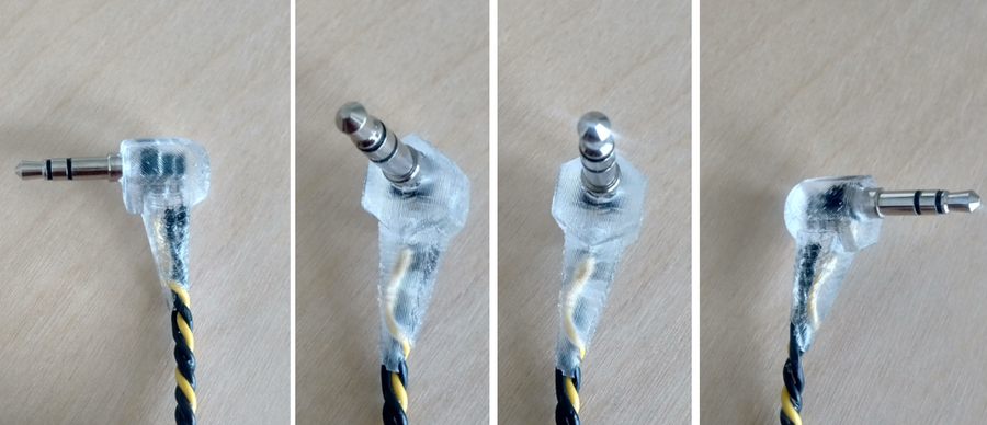
Here are a few pictures of the physical prototype from the original post on my former blog.
Thanks for reading,
Edi