Cad
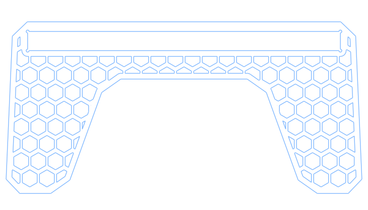
Honeycomb Pattern Monitor Stand
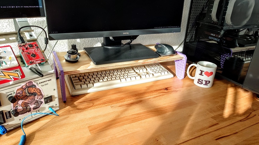
More space when keyboard is not being used just feels nice
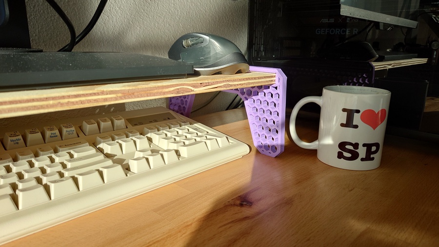
That’s my takeaway after finding a $2 leftover plywood plank at my local hardware store and adding a pair of 3D-printed side supports.
These side supports were created using in cadquery. Nice and simple.
Because the design is fully parametric, getting a snug fit for the plank is effortless, and no hardware is needed. 😎
Here’s the code:
#!/usr/bin/env python3

import cadquery as cq
from cadquery.vis import show

### Monitor Stand with Honeycomb Material-Reduction Holes

## Parameters
# Wooden plank parameters
plank_width = 219.0        # mm, width of the plywood board
plank_thick = 13.4         # mm, thickness of the plywood board

# Monitor stand parameters
base_length = 250.0        # mm, support blank length
support_height = 120.0     # mm, support blank height
support_thick = 10.0       # mm, thickness of the support plate
taper_angle = 5.0          # deg, material removal angle on each side, rect -> trapezoid
round_edges = 10.0         # mm, chamfer on the (A plate blank) edges perpendicular to Z
contour_thick = 4.0        # mm, thickness of the solid outer contour
slot_height = 36.0         # mm, distance from plank slot to the origin
relief_holes = 2.0         # mm, diameter of the semi-holes to relief vertices stress concentration


# Mesh pattern parameters
poly_radius = 6.0          # mm, circumscribed radius of the individual polygon
poly_n = 6                 # int, number of sides of the polygon
spacing = 12.0             # mm, spacing between polygons
x_n = 22                   # int, number of polygons rows (in x)
y_n = 5                    # int, number of polygons collums (in y)

## Part Modelling
# A shaped plate (blank)
blank  = (cq.Sketch()
          .trapezoid(base_length,
                     support_height,
                     90-taper_angle/2)
          )

feet_cutout = (cq.Sketch()
               .trapezoid(base_length/1.5,
                          support_height/1.5,
                          90-taper_angle*4)
               .moved(0, -support_height/6)
               )

Aplate = (blank - feet_cutout).vertices().chamfer(round_edges)
Aplate_offset = Aplate.copy().wires().offset(-contour_thick, mode='r')

# Solid contour around the borders, making the inside of the blank hollow
Ap_extr = cq.Workplane("front").placeSketch(Aplate).extrude(support_thick)
Ap_offset_extr = cq.Workplane("front").placeSketch(Aplate_offset).extrude(support_thick)

borders = Ap_extr - Ap_offset_extr

# Pattern subtraction from an offset of the blank to create a perforated area
# Values here were choosen by trial and error
pattern = (cq.Sketch()
           .rarray(spacing, 2*spacing, x_n, y_n)
           .regularPolygon(poly_radius, poly_n)
           .reset()
           .moved(spacing/2, -spacing)
           .rarray(spacing, 2*spacing, x_n, y_n)
           .regularPolygon(poly_radius, poly_n)
           )

mesh = Aplate_offset.face(pattern, mode='s')

# Creating a slot on the mesh for the wooden plank
plank_slot_sketch  = cq.Sketch().rect(plank_width, plank_thick)
pslot_offset = plank_slot_sketch.copy().wires().offset(contour_thick, mode='r')

mesh_w_slot = mesh.face(pslot_offset.moved(0, slot_height), mode='s')

reliefs = (cq.Sketch()
           .rect(plank_width, plank_thick, mode="c", tag="reliefs")
           .vertices(tag="reliefs")
           .circle(relief_holes/2)
           )

# Reminder: the order of operations is important here, slot_contour has to be after mesh_w_slot
slot_contour = pslot_offset.face(plank_slot_sketch, mode='s').face(reliefs, mode='s')

final_mesh = mesh_w_slot.face(slot_contour.moved(0, slot_height), mode='a')

mesh_extrusion = (cq.Workplane("front")
                  .placeSketch(final_mesh)
                  .extrude(support_thick)
                  )

stand = borders + mesh_extrusion

show(stand)
Most of the code is easy to follow, not many obscure lines on this one. Notable techniques are:
- Using the technique I once proposed on the oficial cadquery documentation to create offsets, using .copy() to prevent mutation of the object
Aplate = (blank - feet_cutout).vertices().chamfer(round_edges)
Aplate_offset = Aplate.copy().wires().offset(-contour_thick, mode='r')
- Just like on theplywood brackets, using .face() to add and subtract sketches
mesh = Aplate_offset.face(pattern, mode='s')
- It may be convenient to use the .moved(x,y) method to place the sketch where you need it, just like:
final_mesh = mesh_w_slot.face(slot_contour.moved(0, slot_height), mode='a')
- Also important to remember, that on the sketch API, a tag is needed to use the vertices() method to distribute a shape
reliefs = (cq.Sketch()
           .rect(plank_width, plank_thick, mode="c", tag="reliefs")
           .vertices(tag="reliefs")
           .circle(relief_holes/2)
           )
That’s it. Not very complicated but not trivial either. The real trick seems to be knowing when to use boolean operations on the sketch method and when to extrude the shapes and go on from there using the fluent API.
📎 Download: Monitor Stand Step File